
1010 · SILICONE NEON FLEX 10×10 IP67
NEON-1010 Top Bend Neon Flex
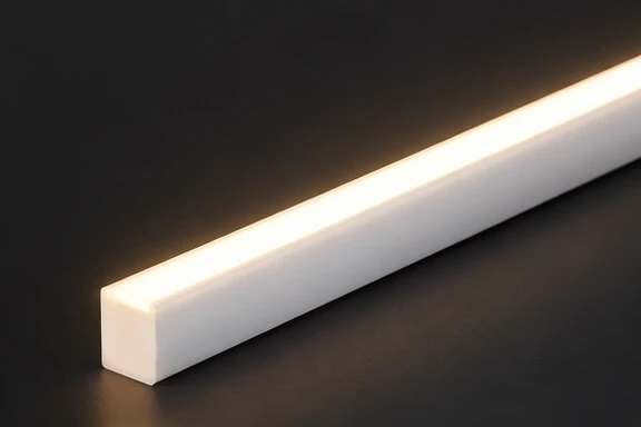
The NEON-1010 is a 1010 top bend neon flex for facades: co-extruded 10x10mm silicone tube with dot-free top emission, DC 24V · 10W/m · 380-580lm/m · CRI 90+ · IP67, 120° beam for outlines, landscapes and signs.
Get Instant QuoteNEON-1010 1010 top bend neon flex tracing a facade outline — 10W/m, IP67.
1010 Neon Flex at a Glance
Power Consumption
Max Lumen Output
Color Rendering
Waterproof Rating
Product Series
One 10×10mm platform — pick your CCT or go custom
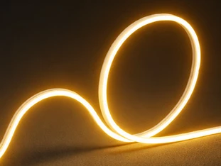
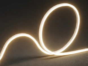
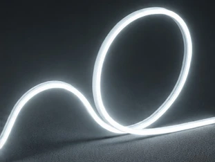
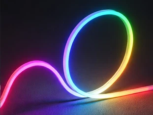
LC-NS1010-Custom
| Length | Cuttable / 5m roll |
|---|---|
| Feed | Bottom / Side / Front |
| Mount | Clip / Profile |
| OEM | Supported |
Specifications
Full parameters of the 1010 co-extruded top-emitting neon flex (per datasheet)
| Model | 1010 co-extruded flat top-emitting | Cross-section | 10 × 10 mm |
|---|---|---|---|
| Weight | 105 g/m | PCB width | 8 mm · 2835 · ≥ 120 leds/m |
| Input voltage | DC 24V (AC→DC driver required) | Power | 10 W/m |
| CCT | 3000K ± 150 / 4000K ± 200 / 6000K ± 300 | SDCM | < 3 |
| Lumen | 380–580 lm/m | Efficacy | 38–58 lm/W |
| CRI | Ra ≥ 90 | Beam angle | 120° |
| Working temp. | -20 ~ 50°C | IP rating | IP67 |
| Packing | 5 m/bag (581 g) · 25 bags/carton (410×410×325 mm, 15.3 kg) | ||
Why NEON-1010 for Facade Outlines
Top-bend 10x10mm silicone line that follows curves rigid fixtures cannot
NEON-1010 Top-Bend Silicone Line for Facade Outlines
The NEON-1010 is a 1010 top bend neon flex for facades: a co-extruded 10x10mm silicone tube that throws a dot-free 120° line from the top face, so building edges, arches and sign strokes render as one continuous glow instead of dotted segments. It runs DC 24V at 10W/m with 380-580lm/m and CRI 90+, and the whole neon flex range in the product index sits apart from track and downlight families.
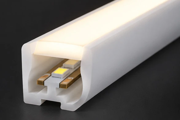
Outdoor survival is structural, not coated on: the IP67 silicone body resists corrosion, acid, alkali and UV across -20 to 50°C, and the 7-part extrusion with light-blocking walls stops side leakage that cheap tubes show at night. Where the ground plane needs dotted path markers rather than lines, see the companion outdoor luminaires for gardens and pathways that handle walkways while this top-emitting silicone neon strip draws the elevation.
Bend behavior decides the fixture: this 1010 neon flex bends in the vertical plane only — min. 300mm fold diameter, 350mm inner diameter on a 5m roll — and never twists, because the inner 8mm PCB is front-mounted. For straight indoor mall lines that must link end to end without bending, choose the LINA-K continuous run linear light for malls; for bending facade outlines, arches and letters, stay with the NEON-1010.
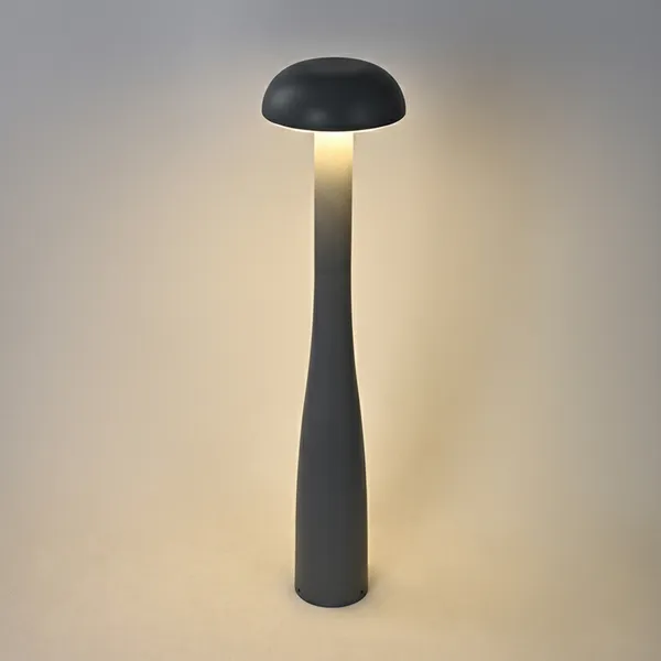
Pair lines with points on the same project: trace the roofline and window frames with this IP67 neon tube for facades, then dot the walkway below with the MUSH-D dome mushroom bollard for garden paths in 30-100cm heights. One supplier covers both the linear outline and the path light, with 5m rolls (581g per bag, 25 bags per carton) packed for export.
NEON-1010 traces stepped edges and arches as one line — rigid bars cannot follow
| Model | Form | Bends | Best for |
|---|---|---|---|
| NEON-1010 | Top-bend silicone line | Vertical plane, 300mm min fold | Facade outlines, arches, signs |
| LINA-K 1614 | Rigid linkable linear | Straight runs only, 10 x 168cm | Mall and boutique ceiling lines |
| MUSH-D | Dome mushroom bollard | Fixed point, 30-100cm heights | Garden paths below the facade |
Size the Bend to the Facade
Cut, bend and CCT choices for outline projects
Cut only at marked 50mm lines; never twist the tube
NEON-1010 CCT Choices for Facade and Landscape
Pick CCT by surface: 3000K warms stone and brick facades, 4000K keeps commercial signage neutral, 6000K cuts through for landscape edges and cool brand walls — all at CRI 90+ with SDCM under 3, so long runs stay visually consistent. One driver rule covers all three: size the 24V supply at total watts times 1.2, feed 5m per run, and never wire the tube to AC mains.
Mount with the emitting face outward — choose by run:
- Screw-down clips for straight parapets — fast fix for level parapets
- Rigid aluminum profiles for long level lines — straight, gap-free runs
- Bendable profiles for arches and letters — curves and sign strokes
The NEON-1010 ships this exact bend-and-cut system as a 10W/m, 380-580lm/m, IP67 package, so project teams can approve one submittal for facade, landscape and sign scopes.
Core Features
Why the 1010 co-extruded tube performs better
Dot-free Emission
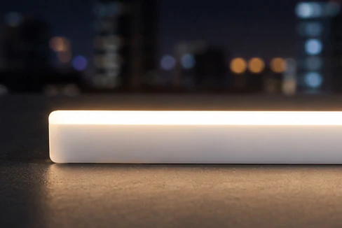
Co-extruded diffuser spreads inner light evenly to the surface — soft, uniform, no spots.
IP67 Waterproof
Silicone body resists corrosion, acid and alkali — built for harsh outdoor weather.
High Consistency
Professional cavity optics keep efficacy high and CCT consistent along the whole run.
Flexible & Tensile
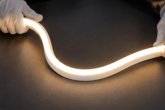
Soft body bends easily for shapes, with strong tensile resistance for field install.
Triple Anti-break
Anti-break beads + PCB + silicone process. 1 m holds 7 kg pull — long runs stay intact.
7-Part Structure
Emitting face, diffuser, clip slot, anti-break rib, light-blocking walls, 8 mm PCB slot, cut window.
1010 in Detail
Structure, light effect and flexibility
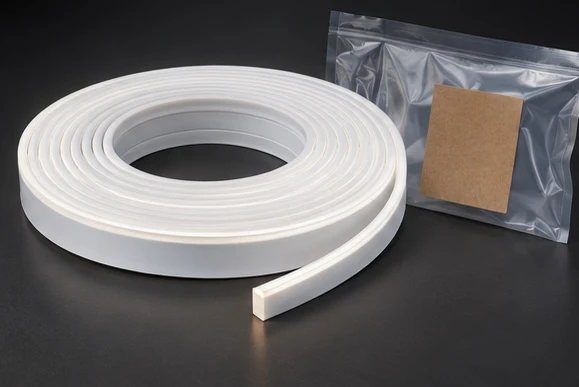
Accessories & Techniques
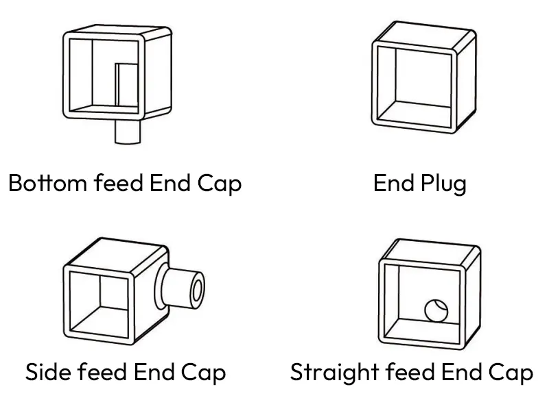
Three Feed Options + Tail Plug
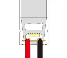
Choose bottom-feed, side-feed or front-feed end caps plus a sealing tail plug. Thread the cable through the cap, solder red (+) / black (−) to the PCB, glue the tube end and let it cure 2–3 hours before moving.
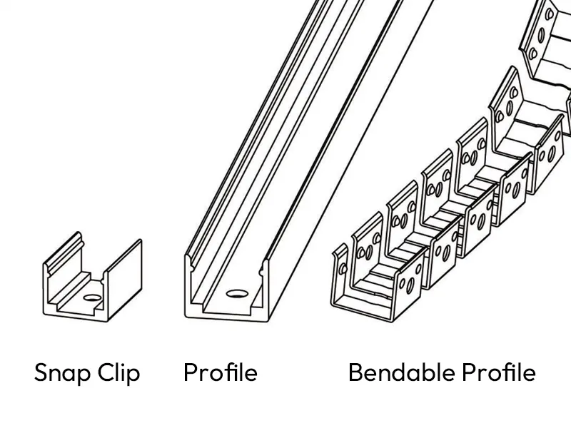
Clips, Profiles & Bendable Channel
Fix with a screw-down clip, a rigid aluminum profile, or a bendable profile for curved designs. Snap the emitting face outward into the channel — clean lines, firm hold.
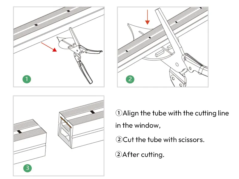
Cut Exactly at the Window
Find the cut line through the bottom window, seat the tube in the shear, and cut in one motion. Only cut at marked lines — never twist the strip, or the inner PCB will break.
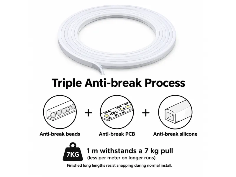
Triple Anti-break Process
Anti-break beads, anti-break PCB and anti-break silicone work together — 1 m withstands a 7 kg pull (less per meter on longer runs). Finished long lengths resist snapping during normal install.
Application Scenes
One flexible tube for outlines, landscapes and interiors



Accessory Installation
Pick the end cap, plug and mount that suits your run — then follow the steps
Side-exit End Cap
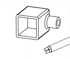
1 Prepare
Have the end cap and cable ready.
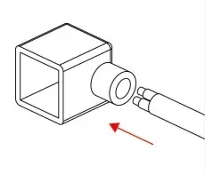
2 Thread
Push the cable through the cap in the arrow direction.
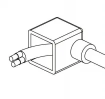
3 Seated
Cable passed through, ready to solder.
4 Solder
Solder red (+) / black (−) wires to the PCB.
5 Glue & cure
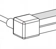
Glue the tube end, push the cap on, rest 2–3 h before moving.
Best for cove and edge runs — Side-exit caps suit runs that sit in a channel or tight against a wall, where the lead must slip out sideways. Common on facade edges, cove slots and sign frames, the cable stays flat in the mounting plane instead of poking out of the tube end.
Front-exit End Cap
1 Prepare
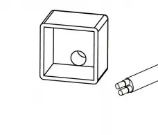
Have the end cap and cable ready.
2 Thread
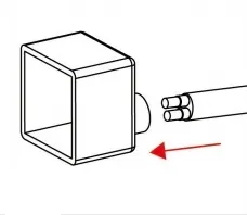
Push the cable through the cap in the arrow direction.
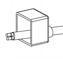
3 Seated
Cable passed through, ready to solder.
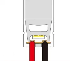
4 Solder
Solder red (+) / black (−) wires to the PCB.
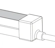
5 Glue & cure
Glue the tube end, push the cap on, rest 2–3 h before moving.
Best for inline feeds — Front-exit caps send the lead straight along the tube axis. Pick them when the driver or junction box sits beyond the end of the run — through-wall feeds on signage, or a joint where the cable continues inline with the light.
Tail Plug
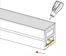
1 Glue
Apply glue evenly around the cut end, push the tail plug on in the arrow direction.
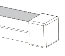
2 Cure
Rest 2–3 h before moving, 12 h before packing.
Required at every cut end — The tail plug closes the unpowered end of the run, so it goes on every cut that is left unpowered. Outdoors it is not optional: the IP67 rating only holds when both ends are sealed and glued.
Clip Mounting
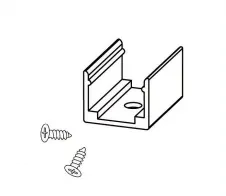
1 Prepare
Have the screws and clip ready.
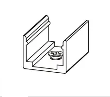
2 Fix
Adjust the clip to position and fasten the screws.
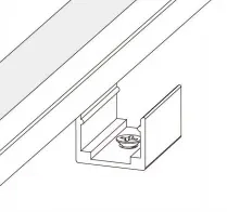
3 Press in
With the emitting face up, press the strip firmly into the clip.
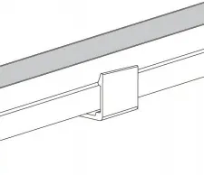
4 Done
Installation complete.
Best for straight surface runs — Screw-down clips are the fastest fix for straight runs on solid, flat surfaces — brick, concrete, render or timber battens. Serviceable by design: pop the tube out of the clip to re-route or replace it later.
Profile Mounting
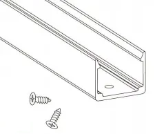
1 Prepare
Have the screws and profile ready.
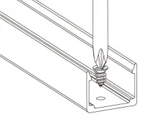
2 Fix
Adjust the profile to position and fasten the screws.
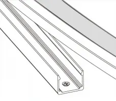
3 Press in
With the emitting face up, press the strip into the profile.
Best for long level lines — A rigid aluminum profile holds a straight, gap-free line and adds mechanical protection plus a small heat sink. Use it on building facades, ceiling coves and corridor reveals where straightness and durability matter more than install speed.
Bendable Profile Mounting
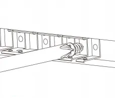
1 Fix
Fix the bendable profile with screws into the pre-cut curved groove.
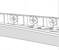
2 Press in
With the emitting face outward, press the strip into the groove.
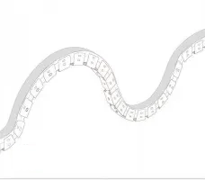
3 Done
Installation complete.
Best for arches and lettering — The bendable profile carries the tube around curves down to its 300mm minimum fold — arches, radiused facades, round columns and curved lettering. Screw it into the pre-cut groove and keep the emitting face outward.
Frequently Asked Questions
You May Also Need
Hand-picked fixtures that pair with this one
Send Message
Fill out the form and we will get back to you as soon as possible